Subjects
Grades
This concept sheet explains the procedures to follow to set up a series circuit or a parallel circuit.
A series circuit is a circuit in which electrons can only flow in one path. In this type of circuit, if a break occurs, the circuit stops working.
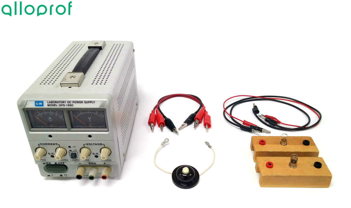
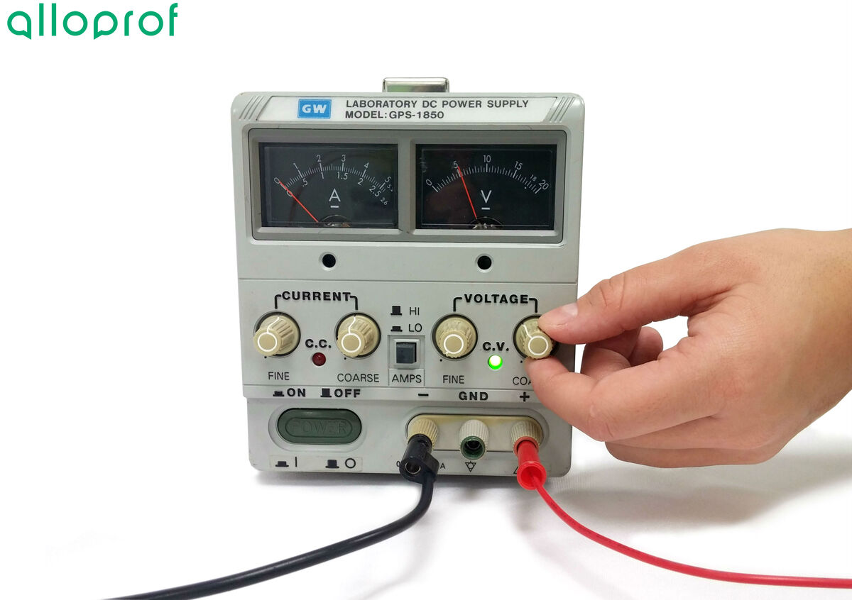
Power source
Electric wires
Crocodile clips
Electric light bulbs
Push button switch

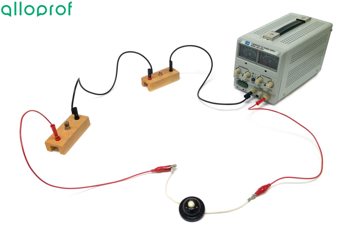
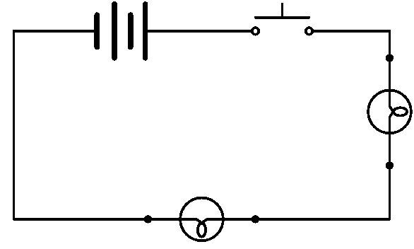
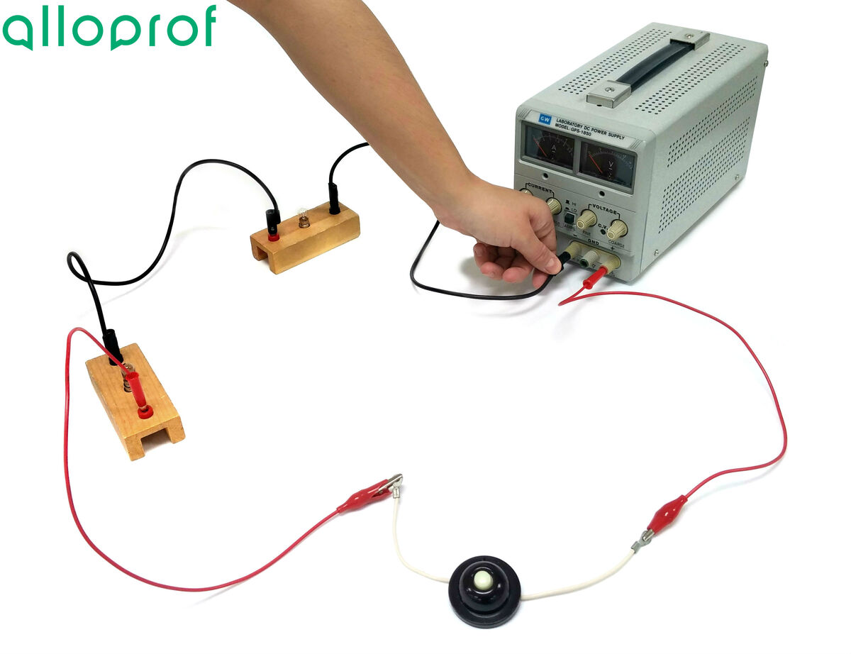
It is preferable to draw a diagram of the electrical circuit before building it in the laboratory (lab). For the purpose of these experiments, the following wiring diagram will be built.
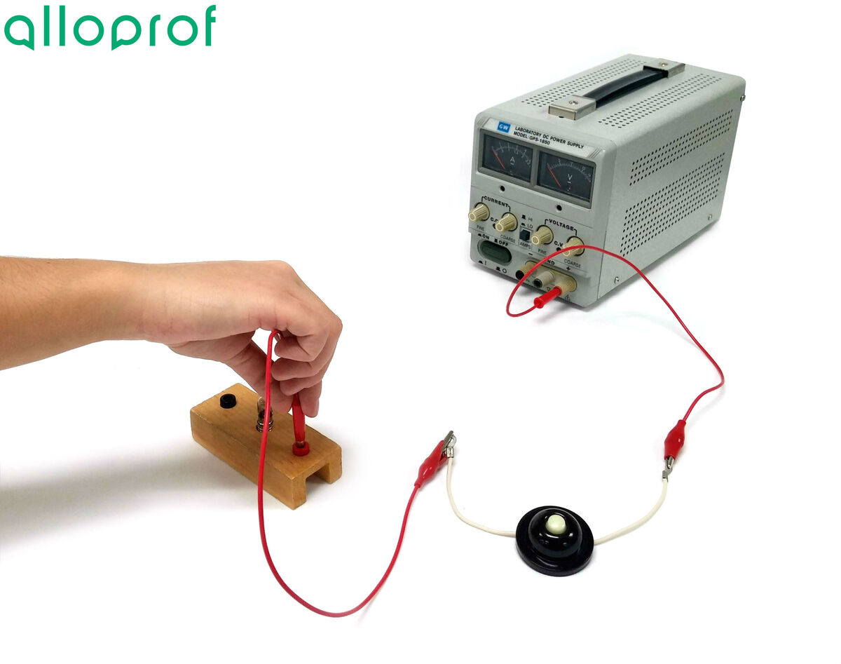
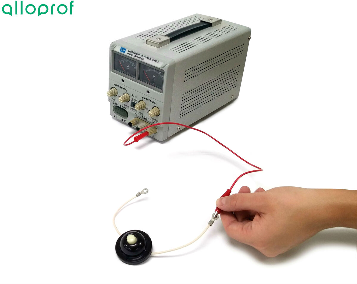
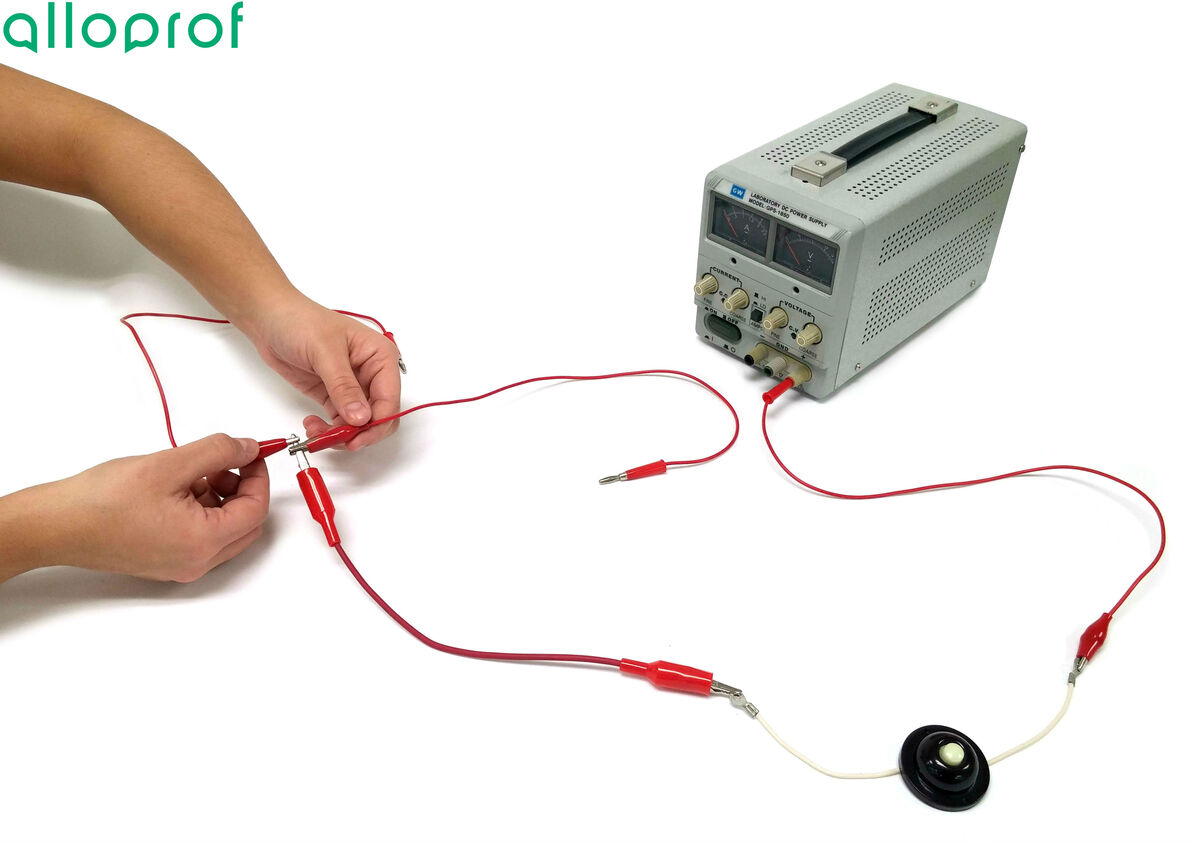
Connect a first wire into the positive terminal of the power source at the push button switch.

The power source should be shut off until the circuit has been completed and verified by a teacher or lab technician.
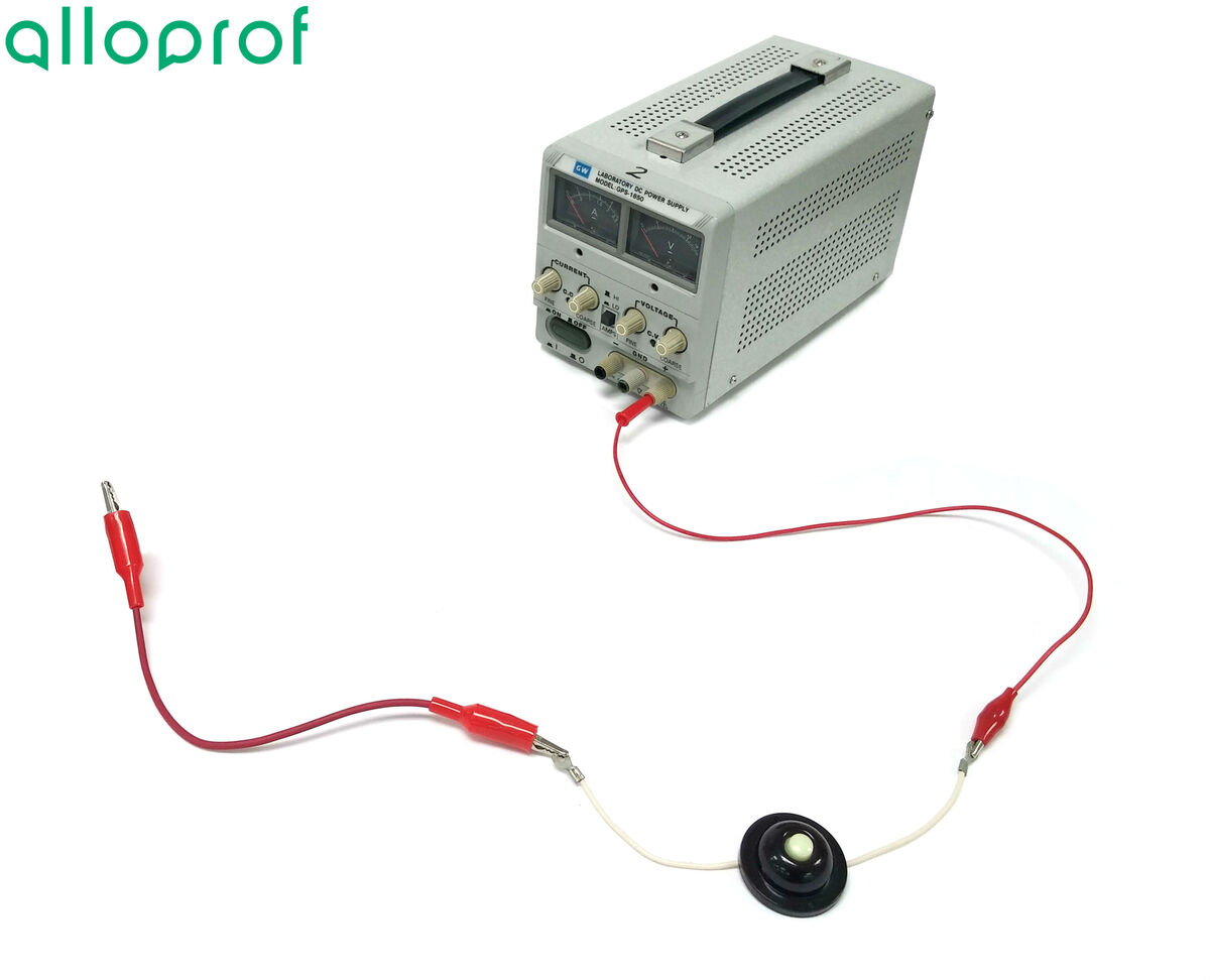
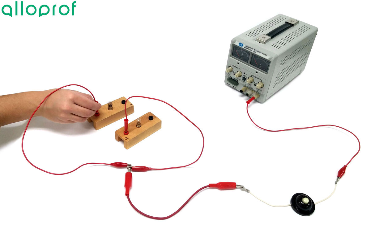
Connect a wire to the other end of the push button switch and attach it to the first bulb. If necessary, use a crocodile clip.
Connect a wire linking the first bulb to the second bulb.
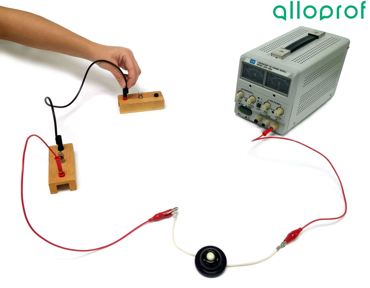
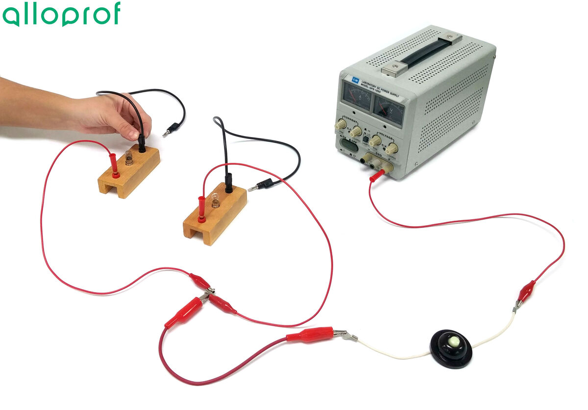
Connect a wire from the second bulb to the negative terminal of the power source.
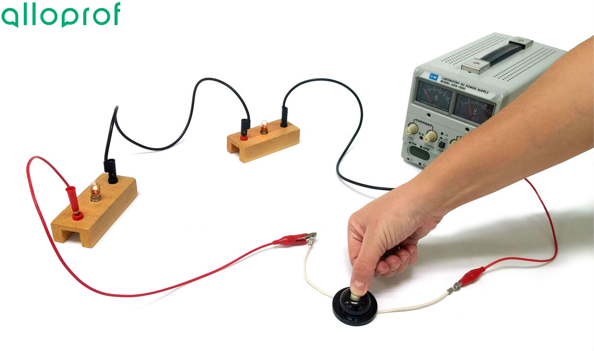
Plug in and turn on the power source, then set the power source to |5\ \text {V}.|
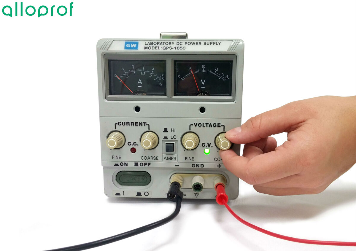
Press the switch.
A parallel circuit is a circuit in which electrons can flow in two or more paths. In this type of circuit, if a break occurs, the circuit can still feed the unbroken branches of the circuit: part of the circuit therefore continues to operate.
Power source
Electric wires
Crocodile clips
Electric light bulbs
Push button switch
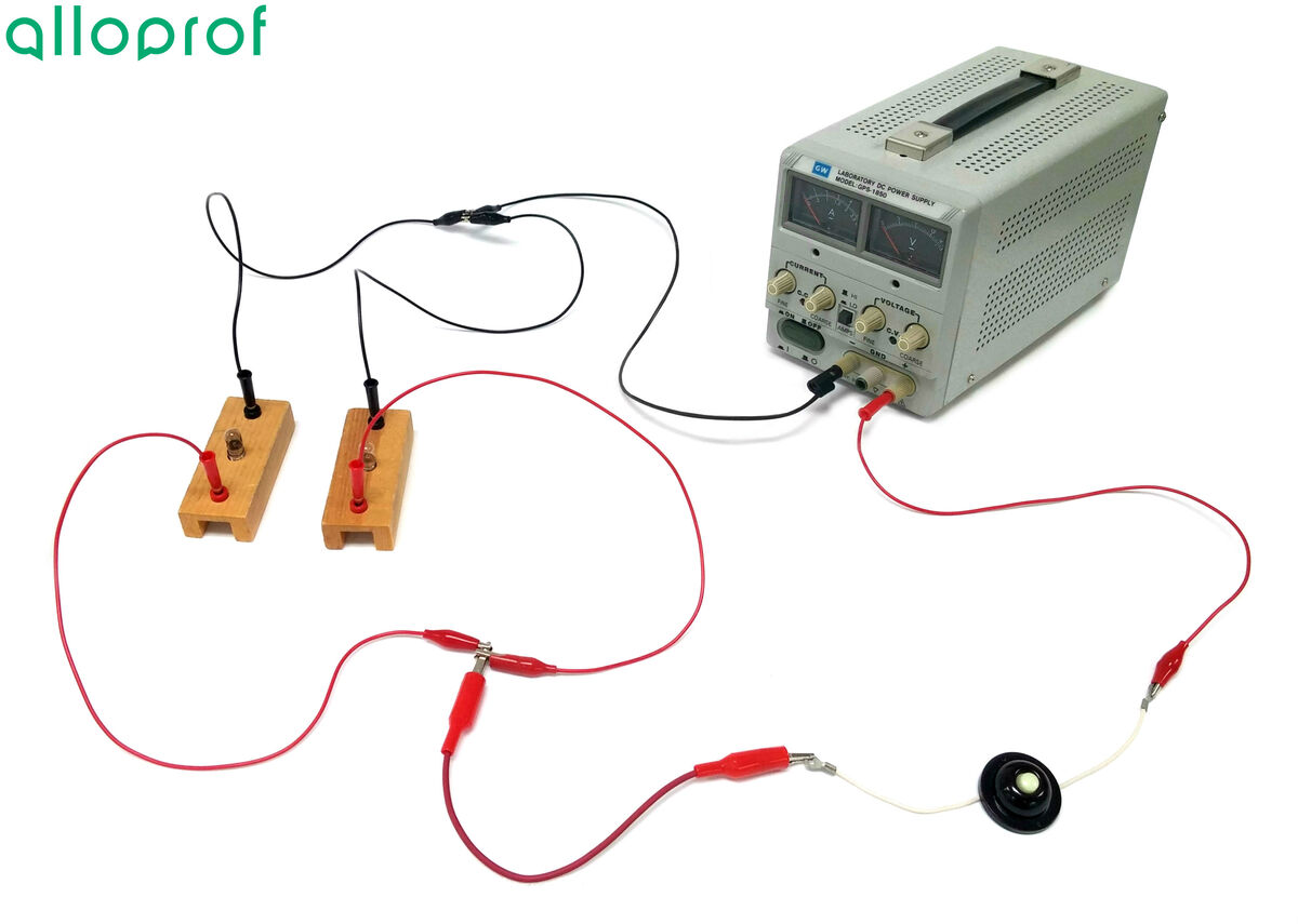
It is preferable to draw a diagram of the electrical circuit before building it in the lab. For the purpose of these experiments, the following electrical diagram will be built.
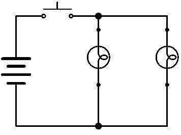
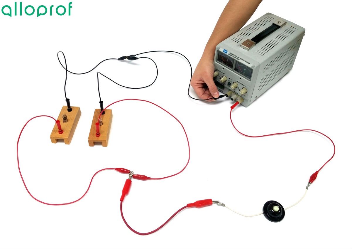
Connect a first wire into the positive terminal of the power source at the push button switch.
It is better to leave the power source closed until the circuit is completed and verified by a teacher or lab technician.
Connect a wire to the other end of the push button switch.
From the free end of this wire, connect two wires to create two separate paths.
Connect a light bulb to each of these wires.
Connect an electric wire to each of the free ends of these bulbs.

Attach the two free ends of the wires together and to this node, connect a new wire.
Connect the last wire to the negative terminal of the power source.
Plug in and turn on the power source, then set the power source to |5\ \text {V}.|
Press the switch.
