Subjects
Grades
This concept sheet explains how to measure current intensity and potential difference.
Current intensity is the speed at which electrons flow in an electrical circuit. It is measured using an ammeter, which must be connected in series in the electrical circuit.
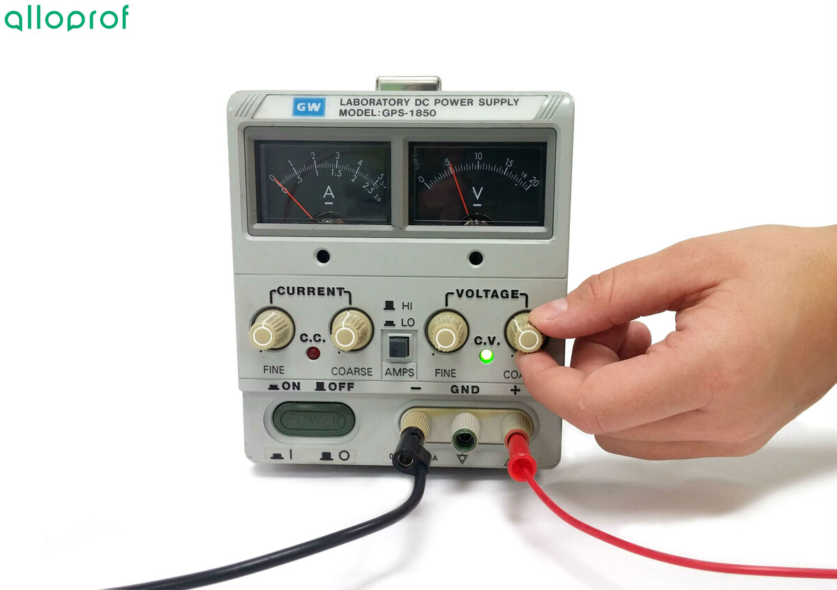
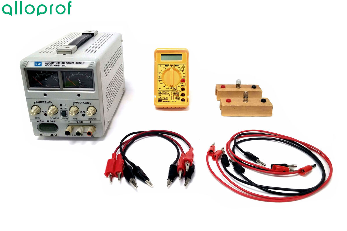
Power source
Electrical wires
Alligator clips
Light bulbs
Multimeter

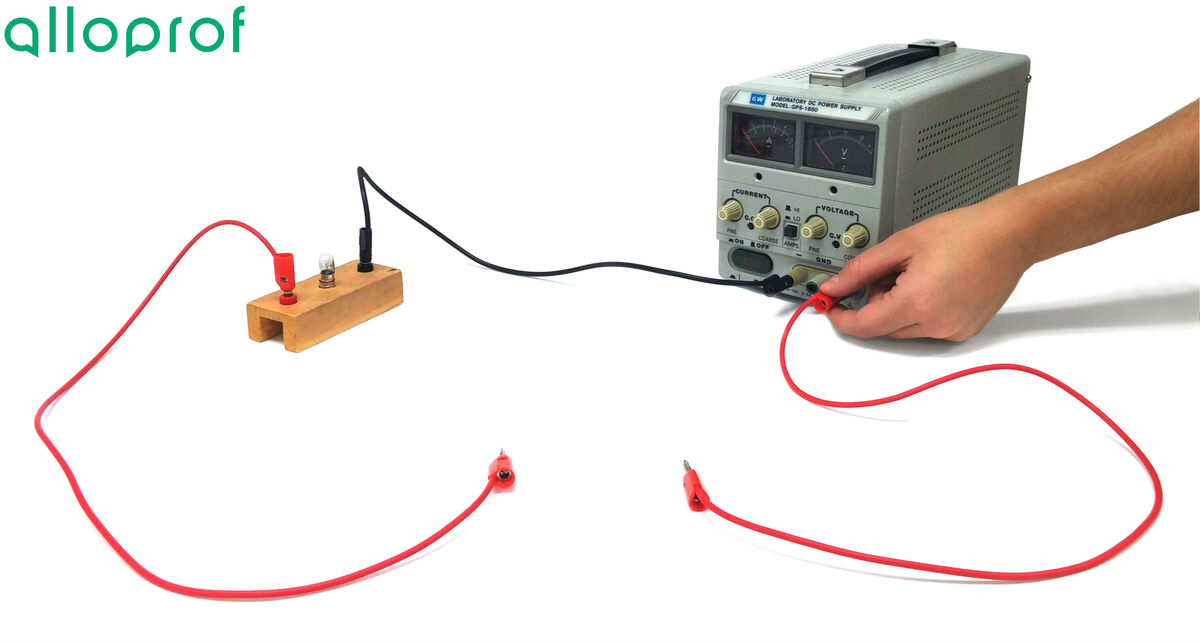
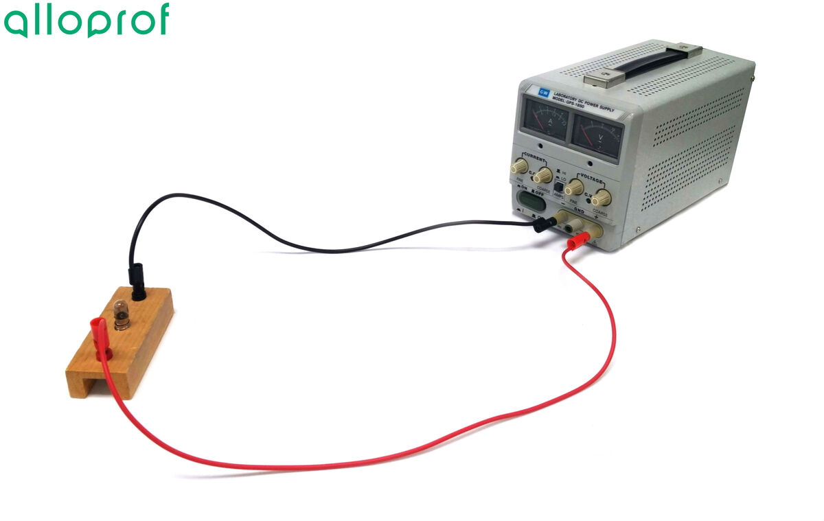
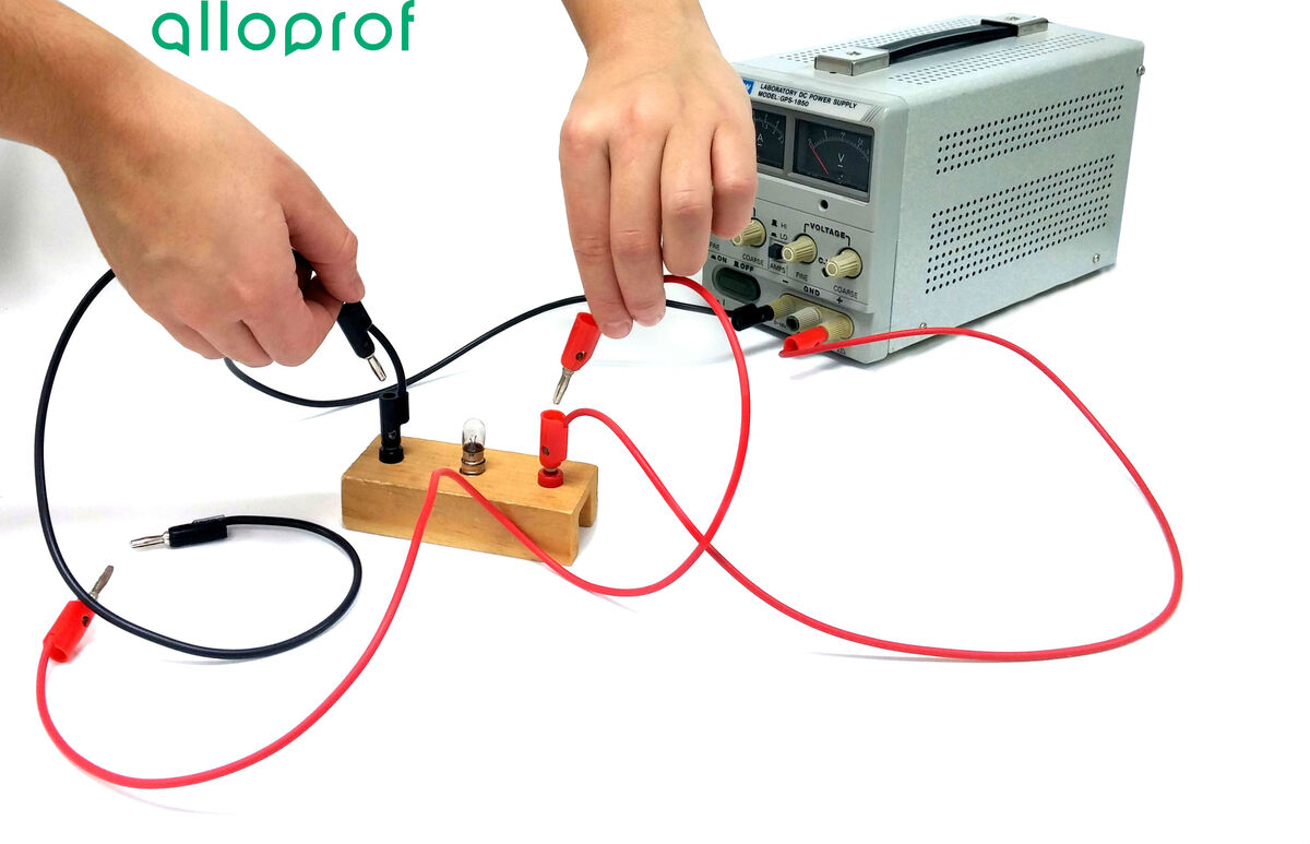
Assemble the circuit.

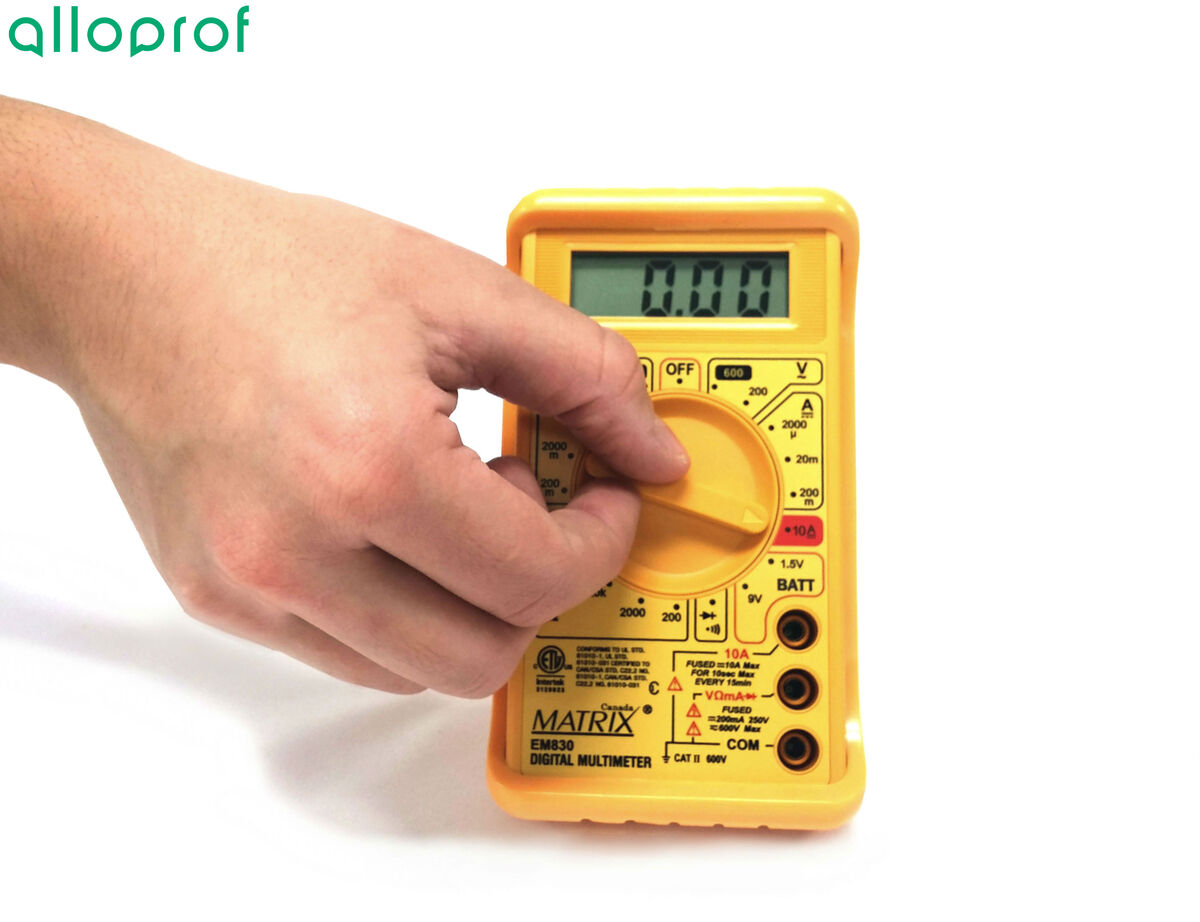
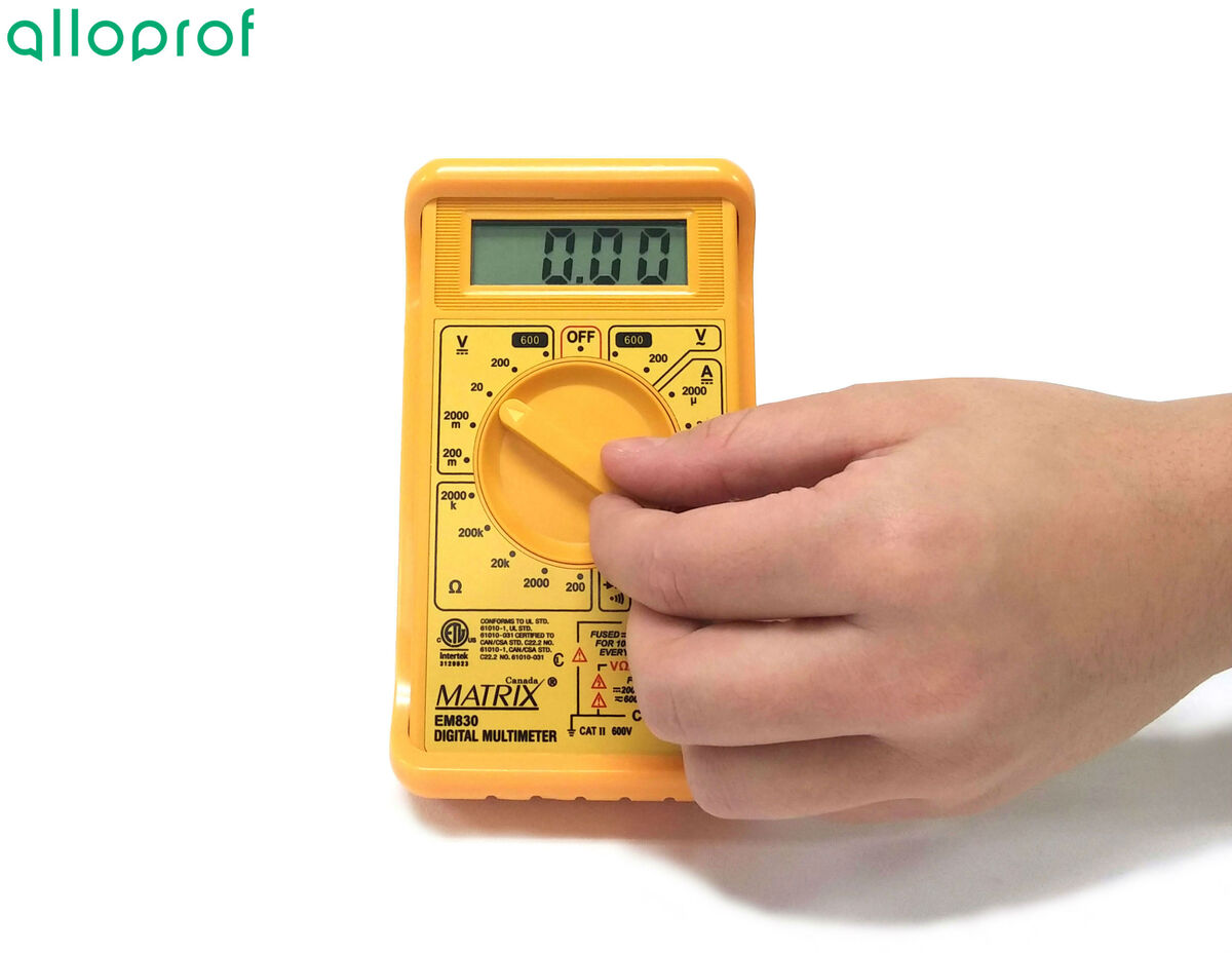
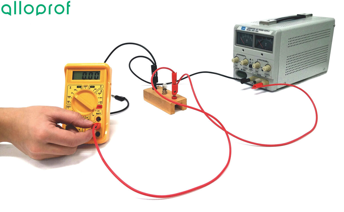
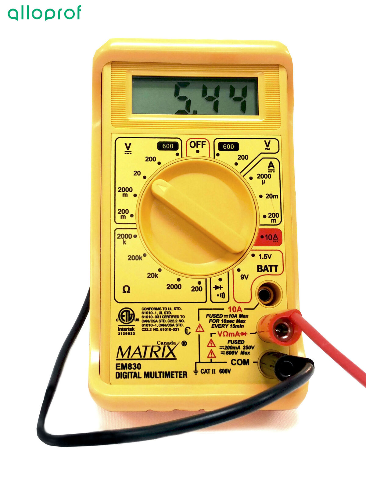
Set the multimeter to the |10\ \text{A}| scale.
Disconnect the positive terminal wire on the source and connect another wire.
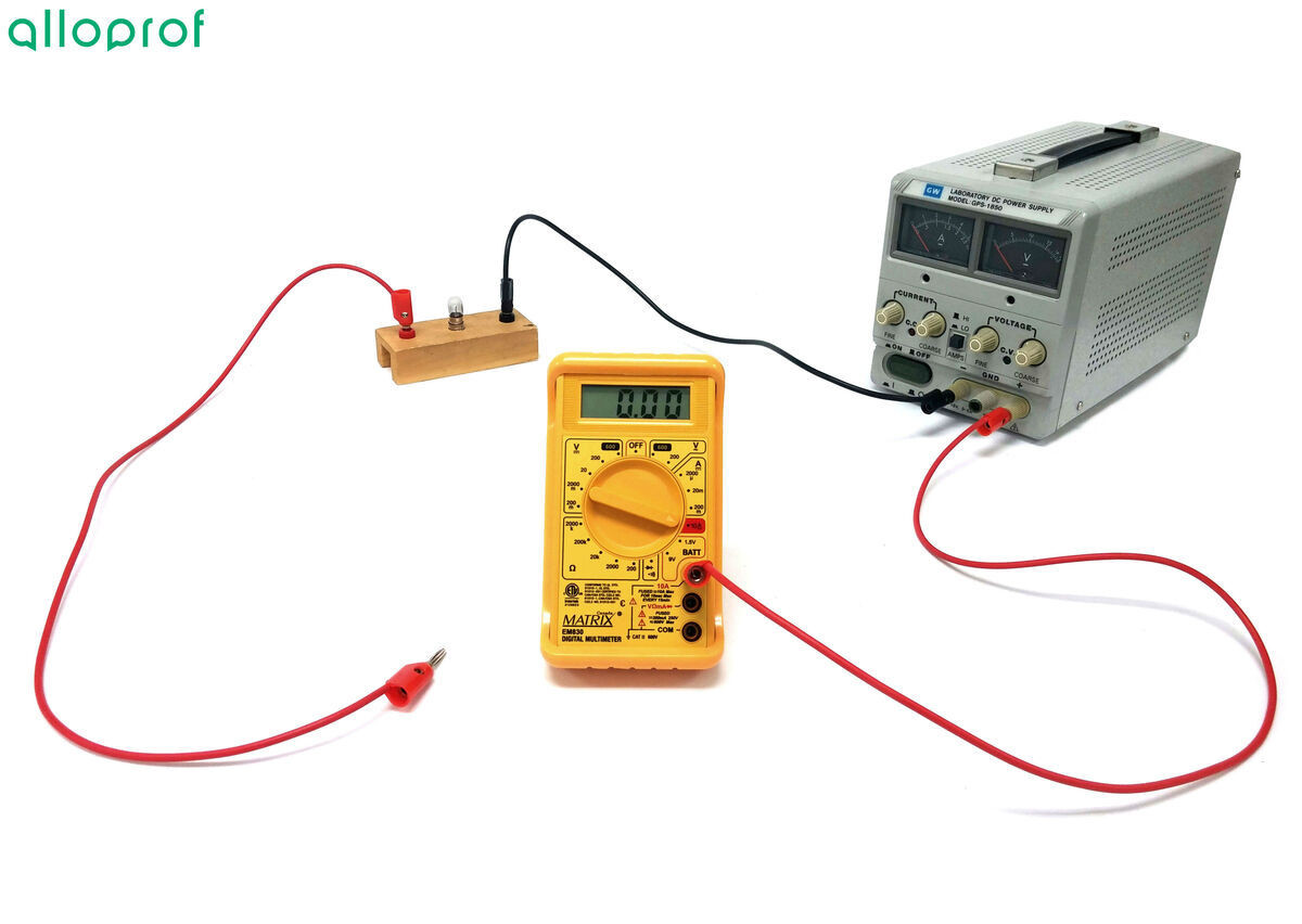
Connect the new wire from the positive terminal of the source to the |10\ \text{A}| port on the multimeter.
If the multimeter or ammeter is connected to the terminals in reverse, with current flowing into the negative terminal and out of the positive terminal, it would display a negative value and could suffer serious damage.
Additionally, the ammeter is connected in series in the circuit, so a wire must be disconnected in order to connect the device. It is best to turn off the power source until the device is properly integrated into the electrical circuit.
Connect the other wire from the light bulb to the COM port on the multimeter.
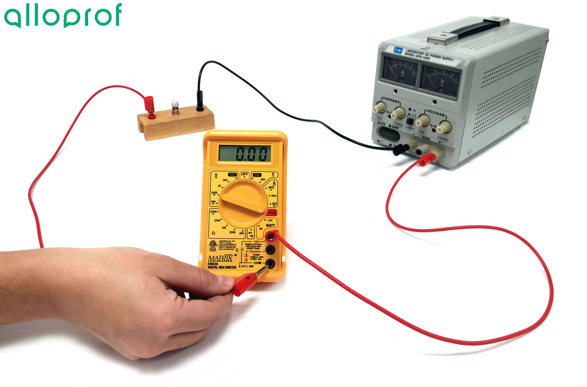
Plug in and turn on the power source. Set it to |5\ \text{V}.|
Check if it is possible to take a reading of the current intensity. If not, select a different scale on the multimeter.
Record the reading displayed on the multimeter.

Disassemble the circuit and put the materials and equipment away.
The potential difference, or voltage, measures the amount of energy in an electrical circuit between two points. It is measured using a voltmeter, which must be connected in parallel with the electrical circuit.
Power source
Electrical wires
Alligator clips
Light bulbs
Multimeter
Assemble the circuit.
Set the multimeter to the |20\ \text {V}| scale.
Add a wire to each terminal of the light bulb so that the multimeter is in parallel with the circuit.
If the multimeter or voltmeter is connected to the terminals in reverse, with current flowing into the negative terminal and out of the positive terminal, it would display a negative value and could suffer serious damage.
Connect the wire from the light bulb to the VΩmA port on the multimeter.
Connect the other wire coming from the bulb to the COM port on the multimeter.
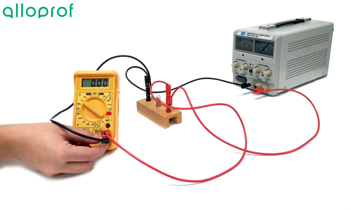
Plug in and turn on the power source. Set it to |5\ \text {V}.|

Check if it is possible to take a reading of the potential difference. If not, select a different scale on the multimeter.
Record the reading displayed on the device.
Disassemble the circuit and put the materials and equipment away.