Subjects
Grades
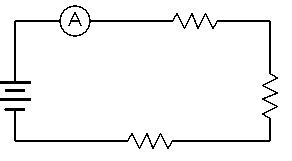
An ammeter measures the current intensity flowing in a given section of an electrical circuit.
Ammeters are always connected in series with the device in which the current is being measured.
To avoid damaging the ammeter, it is recommended to always take a reading using the highest range (the range that can provide the highest electrical current value). The range can then be reduced to get the most accurate reading of the electrical current.
The ammeter's range takes into account the deflection of the electrons. The device is calibrated with this in mind. An ammeter may have multiple ranges.
Inside an ammeter
Ammeters are derived from galvanometers. The way they work is relatively simple. The electrical current enters the device and, since the shunt resistor has a very low resistance, most of the electrical current will flow through this resistor. A small electrical current will flow through the moving coil, or solenoid, generating a magnetic field and deflecting the moving coil, which is surrounded by a permanent magnet. The pointer is attached to the moving coil and moves with it.
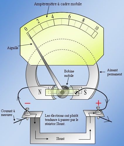
The stronger the electrical current, the more electrons flow through the moving coil. The magnetic field will also become stronger, deflecting the coil even further, and the pointer will indicate a higher current measurement.
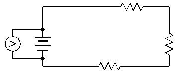
Voltmeters are used to measure the potential difference (voltage) in an electrical circuit.
Voltmeters are always connected in parallel with the device on which the potential difference is being measured.
A voltmeter may have multiple ranges. To avoid damaging the voltmeter, it is recommended to always start a reading using the highest range (the range that can provide the highest potential difference value). The range can then be reduced to get the most accurate reading of the potential difference.
Inside a voltmeter
Voltmeters are derived from galvanometers. Since voltmeters do not measure electrical current, high-resistance coils are used to limit the current’s access to the device. Voltmeters attract only a very small portion of the current flowing along the circuit. The weak electrical current entering the device flows through the moving coil, or solenoid, generating a magnetic field and deflecting the moving coil, which is surrounded by a permanent magnet. Like in ammeters, there is a pointer attached to the moving coil that moves with it.
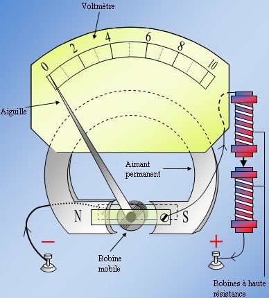
The stronger the electrical current, the more electrons flow through the moving coil. The magnetic field will also become stronger, deflecting the coil even further, and the pointer will indicate a higher potential difference. The device is calibrated with this in mind.
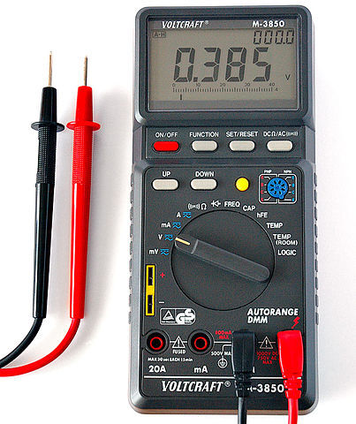
Multimeters are all-in-one devices that combine the functions of voltmeters, ammeters and ohmmeters.
Multimeters make it possible to measure current intensity, potential difference and electrical resistance using a single device.
Ohmmeters only measure the electrical resistance of a resistor or electrical circuit. They work in one of two ways. The device can apply a current intensity through the unknown resistor using a current generator, then measure the resulting potential difference. Alternatively, the device can apply potential difference to the resistor terminals or circuit using a voltage generator, and measure the current intensity flowing through it. Regardless of the method used, ohmmeters rely on the Ohm’s law to determine the resistance.