Subjects
Grades
The main types of projections used in technical drawing are:
Some concepts are useful for understanding and clearly distinguishing the different types of projections.
A projection is the representation of a three-dimensional object on a two-dimensional surface.
In technical drawing, as in artistic drawing, difficulties arise when trying to correctly draw an object in three dimensions on a drafting sheet that has only two dimensions. In order to show the three dimensions of the object as well as its characteristics in detail, different types of projections are used.
Here is the same camera shown in three different projections.
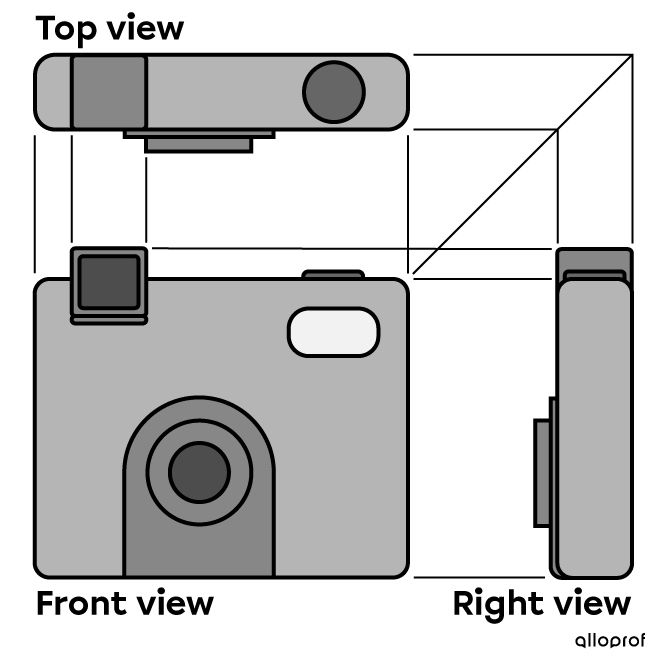
Multiview projection of a camera
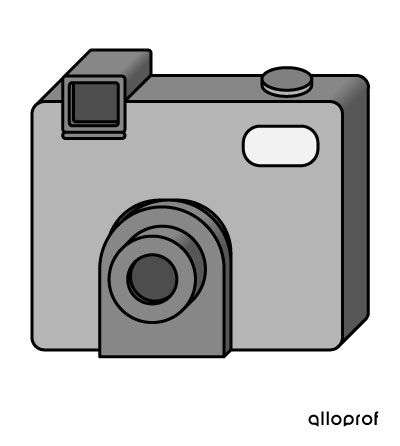
Oblique projection of a camera
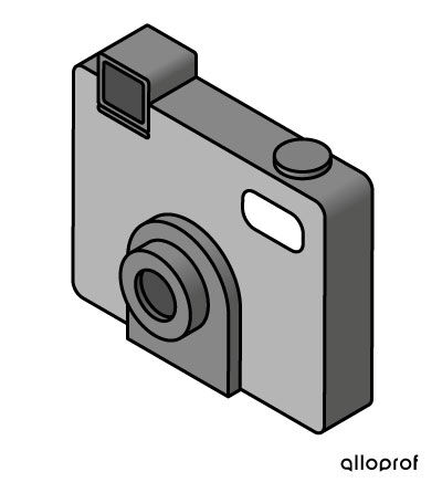
Isometric projection of a camera
In order to fully understand the differences between the various types of projections, it is essential to use the correct terms to describe the space occupied by an object. By convention, the following terminology is used in technical drawing.
|
Concept |
Description |
Example |
|---|---|---|
|
|
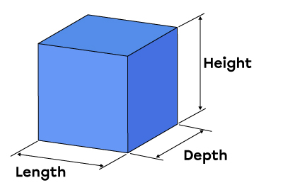
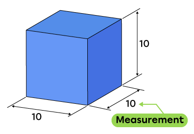
An object generally occupies three dimensions in space: length, height, and depth (or width). |
 |
|
Measurement |
The measurements of an object correspond to numerical values associated with a unit of measurement. |
 |
|
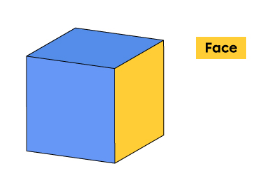
Face |
A face is a flat surface. It has two dimensions (for example, a square). |
 |
|
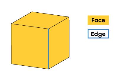
Edge |
An edge is a line. It has only one dimension. It indicates the limits of a face or the common boundary between two faces. |
 |
|
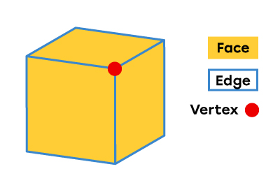
Vertex |
A vertex is a point. It has no dimension. It designates the points of intersection between two or more edges. |
 |
An orthogonal projection is a projection in which all the visual rays starting from the object’s vertices are directed perpendicularly towards an observer positioned in front of the drafting sheet.
This projection category includes multiview projection and isometric projection.
The types of projections differ from each other in two respects: the position of the object relative to the drafting sheet, and the angle between the visual rays and the sheet.
In the case of multiview projection and isometric projection, the visual rays from the vertices of an object are perpendicular to the sheet. This means that an observer can perceive the object in multiview projection (one view at a time) or in isometric projection by being positioned directly in front of the object. These projections thus belong to the category of orthogonal projections.
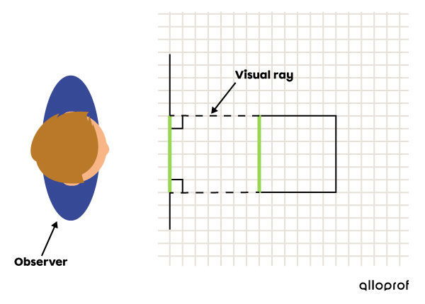
Visual rays in a multiview projection
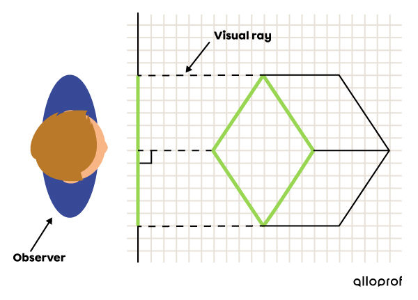
Visual rays in an isometric projection
In contrast, in the oblique projection, the visual rays from the vertices are oblique to the drafting sheet. In other words, it is impossible to perceive an object in oblique projection if the observer is positioned directly in front of the object.
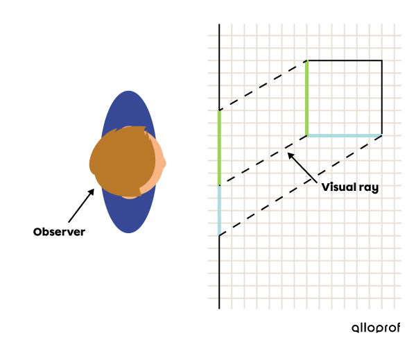
Orientation of the visual rays in an oblique projection
Perspective projections are types of projections that give the impression of depth.
There are different ways to represent the depth of an object. The impression of depth can be created by using a vanishing point or by using parallel axis lines. These two methods are shown below.
Like central projections in mathematics, perspective projection with vanishing points is used to create the illusion of depth of an object. In this case, the lines reproducing the effect of depth all converge towards one or more points called vanishing points.
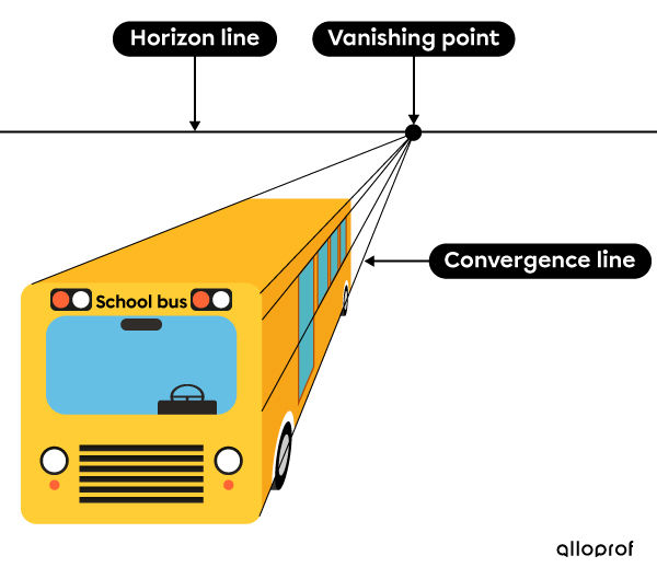
Bus in a perspective projection with vanishing point
The use of a vanishing point in a perspective projection is not recommended in technical drawing as the actual proportions of the object are not preserved. In fact, as the convergence lines all converge towards the same vanishing point, the dimensions of the most distant faces are reduced. The vanishing point therefore only provides an overview of the depth. However, this method provides a representation that resembles what the eye of an observer perceives. For example, perspective projection with a vanishing point creates the same depth illusion as photography.
Like parallel projections in mathematics, perspective projection using parallel axes creates the illusion of depth of a projection without the use of a vanishing point. Examples of this are isometric projection and oblique projection. Indeed, in these representations, all the lines related to the depth of an object are parallel to each other. Also, since they do not use a vanishing point, these projections are less consistent with what an observer's eye perceives.

Bus in a perspective isometric representation

Bus in an oblique perspective representation