Subjects
Grades
The technical drawing of an object facilitates its design and makes it possible to present its characteristics for the purpose of its manufacture. Since the design and manufacture of objects are processes involving a large number of people, there is a need for standardized practices to ensure good communication between the different people involved.
Basic lines are lines whose appearance and meaning are governed by international conventions.
A technical drawing combines various types of basic lines to show all the characteristics and details of an object. Each type of line must be used according to its function defined by convention.
Construction lines are used to sketch the drawing. They must be represented by a thin, continuous line. They are sometimes erased in the final drawing.

Visible contour lines indicate the outlines as well as the visible details of an object. They must be represented by a medium and continuous line.

Hidden contour lines indicate hidden outlines or details of an object. They must be represented by a medium, dotted line.

Dimension lines indicate the boundaries of a segment. These are displayed as two arrows in opposite directions between which we find the dimension of the segment. Each arrow points to an extension line. Dimension lines are represented by a thin, continuous line.

Extension lines delimit the endpoints of dimension lines. They must be represented by a short, thin, and continuous line.

Centre lines indicate the symmetry of an object. The intersection of two perpendicular centre lines indicate the centre of a circle. If needed, a centre line can be extended and used as an extension line. Centre lines should be represented by a thin, dashed line.

Cutting plane lines indicate the location of a section or cross-section. Its arrows point the direction an observer must look to see the drawing of the section or cross-section. Axis lines must be represented by a solid or dashed bold line.

The hatched lines indicate a surface intersected by a cutting plane line. They must be represented by thin, parallel lines.

Leader lines associate information (diameter, radius, etc.) with a specific area pointed to by an arrow. They must be represented by a thin line marking an angle of 30° or 45°.

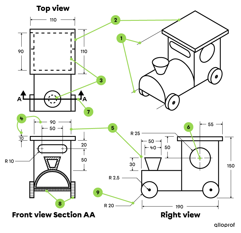
The following example shows the technical drawing of a model train locomotive according to different types of projection. You can see all the basic lines presented above.
|
Identification on the drawing |
Type of lines |
Appearance of lines |
|---|---|---|
|
1 |
Fine and continuous lines |
|
|
2 |
Medium and solid lines |
|
|
3 |
Medium and dotted lines |
|
|
4 |
Thin and continuous lines |
|
|
5 |
Short, thin, and continuous lines |
|
|
6 |
Thin and continuous lines |
|
|
7 |
Bold, solid or dotted lines |
|
|
8 |
Thin and parallel lines |
|
|
9 |
Thin lines with a 30° or 45° angle |