Subjects
Grades
Cross-sections and sections are used in technical drawings to show more information about the hidden details of an object in order to feature these elements.
A cross-section is the drawing of an object that is imagined to be cut by a cutting plane line in order to show hidden details that cannot be seen from other views.
In a technical drawing such as the manufacturing drawing of an object, for example, details that are not visible are represented by hidden contour lines, as specified by the basic lines. However, sometimes these details are too numerous and they are superimposed. Therefore, representing the different views of the object in a multiview projection, for example, is not efficient. Some details inside the object may not be visible or the use of hidden contour lines could make interpreting the drawing difficult.
A cross-sectional view makes the hidden details more apparent. For example, when cutting a cake, we can see the different layers of icing or a fruit filling that was not visible from the outside. A cross-section makes it possible to do the same with an object.
A cross-section therefore offers a two-dimensional representation of one of the faces of the object (front view, right side view, top view, etc.) at the point indicated by a cutting plane line.
To draw the cross-section of a technical object, certain steps must be followed.
Place the cutting plane line at the point on the object where the cut is to be made to present more detail.
Draw arrows that point to the cross-section of the object to be retained at the end of this line.
Identify the cutting plane line by writing two capital letters at each end.
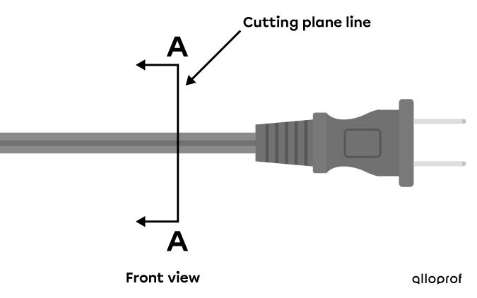
Position and identification of a cutting plane line on a power cable
Remove the part of the object that is opposite to the direction of the cutting plane line. Only the part in the direction pointed to by the arrows should be retained.

Remaining part of the power cable after cutting away a section
Rotate the object so that the cut side is facing the viewer. All contour lines should be solid.
When cutting the power cable, it can be seen that it contains two wires.

The power cable cut and turned in front of the observer
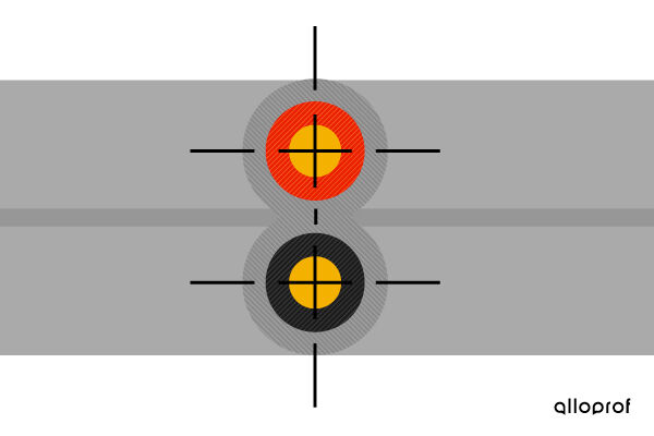
Identify the areas removed when cutting the object by adding hatched lines. Plane lines are added to the symmetrical components of the object if necessary.

Cross-sectional view of a power cable
In step one, a cutting plane is used rather than a cutting plane line if the object is represented in isometric projection.
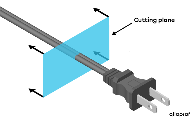
Cutting plane of a power cable in isometric projection
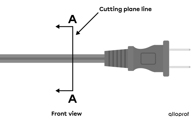
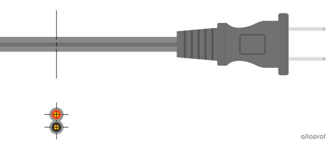
Cutting plane line on a power cable in front view
In cross-sectional views, there are usually no more hidden contour lines to represent. Indeed, a cross-section is used to display the details of an object that were not visible at the beginning.
A section is the representation of a part of the visible surface of an object on along cutting plane.
Unlike a cross-section, which shows all of the part of the object covered by the cutting plane line and its details, a section shows only a part of the surface located on the cutting plane of that object.
Sections are useful in multiview projection because they highlight the relief of the parts and hidden details.
By convention, the cutting plane used to describe a section is represented using a centre line, while the section view itself is drawn using visible contour lines and hatched lines.
Two methods are used to illustrate a section.
The aligned sectional view is created when the section to represent is drawn directly on the representation of the object. To do this, rotate the section on itself in the cutting plane so that it is positioned facing the observer.
Aligned sectional view of a power cable
The offset sectional view, like the aligned sectional view, is created when the section must be rotated on itself so that it faces the viewer. But in this case, it is drawn outside the object representation. In fact, this section is drawn as an extension of the centre line.
The offset sectional view is used to not interfere with the clarity of the drawing or its comprehension.
Offset sectional view of a power cable