Subjects
Grades
A transistor is an electronic component capable of blocking or amplifying electric current.
Transistors are used to control the flow and intensity of current using a low voltage and a low-intensity current.
A transistor consists of three conductive rods, also called terminals. They are generally identified by the letters b, c and e: the base (b), the collector (c) and the emitter (e).
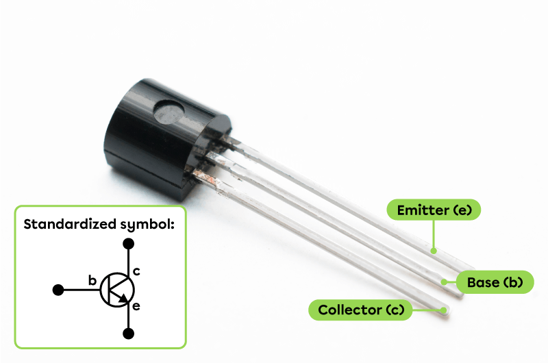
A transistor
|
Rod |
Role |
|---|---|
|
Base (b) |
|
|
Emitter (e) |
|
|
Collector (c) |
|
The voltage applied to the base determines whether or not current flows through the collector. It also determines how much current, if any, flows in the collector.
When the voltage applied to the base is too low, a low-intensity current flows between the base and the emitter, and no current is transmitted to the collector. Generally speaking, a voltage of at least |0.6\ \text{V}| must be applied to the base to enable the current to flow to the collector. This voltage must be varied between |0.6\ \text{V}| and |0.8\ \text{V}| to modify the intensity of the current transmitted to the collector.
The following electrical diagrams show a light-emitting diode (LED) whose light activation and intensity are controlled by a transistor.
In the electrical circuit, note that:
The base (b) and the emitter (e) form a first loop with the low-voltage current source.
The emitter (e) and the collector (c) form a second loop with the high-voltage current source and the LED powered by this source.
The brightness of the LED indicates whether the intensity of the current flowing through the collector (c) is low or high.
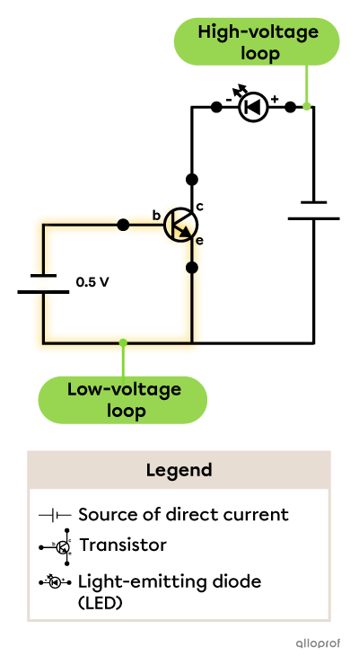
When the voltage applied to the base is |0.5\ \text{V},| it is too low to enable the current to flow through the collector, so the LED remains off. In this situation, the transistor blocks the current flow to the LED.
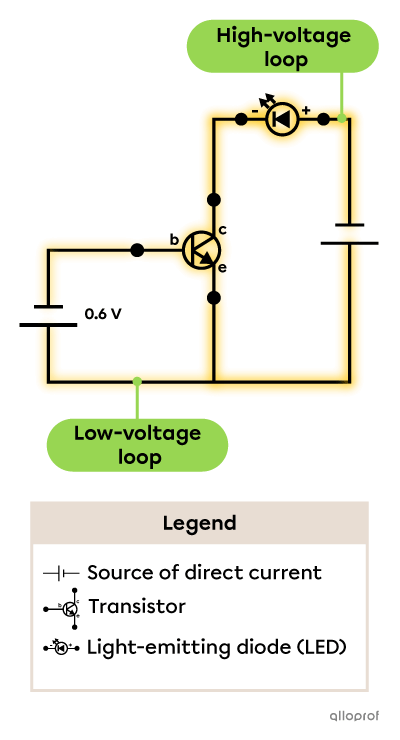
When the voltage applied to the base is |0.6\ \text{V},| it is enough to enable the current to flow through the collector, so the LED turns on, however it emits very little light.
In this situation, the current in the high-voltage loop is amplified relative to the current in the low-voltage loop.
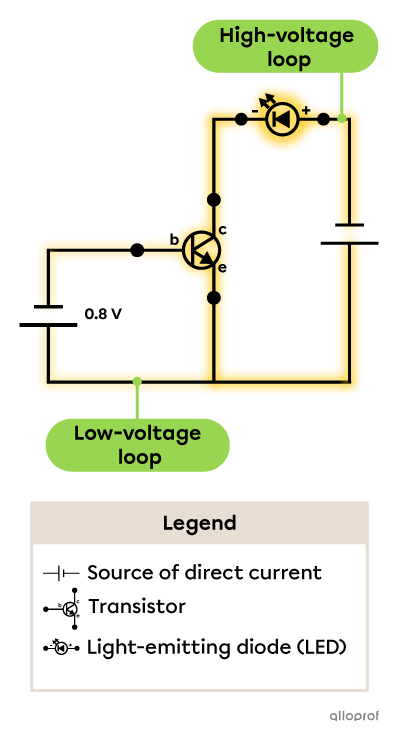
When the voltage applied to the base is |0.8\ \text{V},| the maximum-intensity current flows through the collector, so the LED turns on and it emits the maximum amount of light.
In this situation, the current in the high-voltage loop is even more amplified relative to the current in the low-voltage loop.
A computer's microprocessor contains microscopic transistors that act like small switches, allowing or preventing the current flow.
When the current flows, this signal corresponds to the number 1. When the current doesn't flow, this signal corresponds to the number 0. Computer information and operations are coded using the binary system made up of sequences of 0s and 1s.

A microprocessor